Posts

Showing posts from November, 2020

Some news of the build
Image
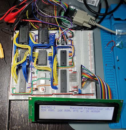
 I haven't been very active lately on the blog. You know, life! That and I was working on the monitor program for my build. Anyway, above is a picture of my build on this day. Getting the 40x4 display working was a pain, but I managed to figure it out. I'm still debating if I should use the single 40x4 display, or a 20x4 display AND a graphical display. The pros and cons: The 40x4 LCD actually operates as 2 independent LCDs and requires 2 enable pins for top and bottom portions. So this makes it harder to code for. You have to admit, it looks pretty spiffy. However, the 20x4 display is easier to code for. I am also considering a graphical display, possibly as a second display? Time and budget will tell... stay tuned.
New memory map, simple EEPLD programming

Image
And here I thought that WinCupl was a beast to comprehend. But it turns out I was missing some information. The magic happens with fields. All I had to do is specify addresses in my equations to let WinCupl work out the logic for me. My first try was to use pure logic gates. And this failed for me when I tried to address IO within the range of ROM and RAM. Live and learn, I am after all new at this. Behold the simplicity of WinCupl's power: Name       Mainboard Logic Decode v2; PartNo     ATF22V10C ; Date       2020-11-22 ; Revision   01 ; Designer   The Micro Hobbyist ; Company    Self ; Assembly   6502 mainboard logic ; Location   U105 ; Device     G22V10; /* *************** INPUT PINS *********************/ PIN 1   =  CLK;      /* Clock */ PIN 2   =  A15; PIN 3   =  A14; PIN 4   =  A13; PIN 5   =  A12; PIN 6   =  A11; PIN 7   =  A10; PIN 8   =  A9; PIN 9   =  A8; PIN 10  =  IRQ0;    /* IRQ from VIA */ PIN 11  =  IRQ1;    /* IRQ from ACIA */ PIN 13  =  RW;      /* Read Write